It’s been a long way around but we’re finally here. Let’s talk about the piece of technology that’s at the center of it all – the turbine.
As always if there is some terminology that’s confusing – feel free to look at the previous installments in the series.
.jpg)
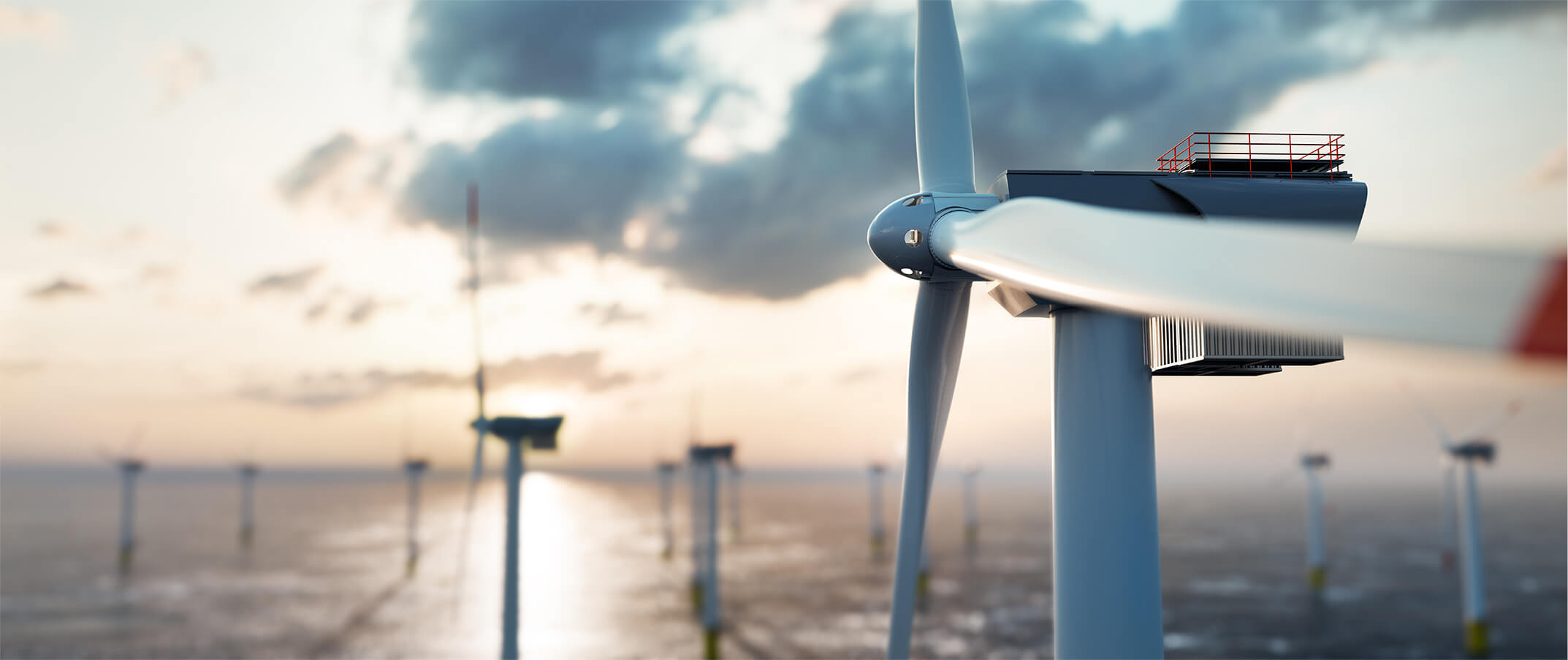
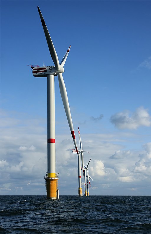
The turbine pictured above is the currently most widespread type of wind turbine.
Wind turbine designs have varied widely, but in the interest of brevity we’ll stick to discussing how the most common model looks. Note that none of these design parameters are “set in stone” as the most efficient way to design a turbine – it's simply the most common one currently for a variety of reasons.
The “standard turbine” is a horizontal-axis turbine with three blades, where the blades are “in front” of the tower with respect to the wind direction. It can pitch (rotate) its blades to regulate how much power it produces, and it’s a so-called variable-speed turbine which means that the rotor doesn’t always rotate at the same speed.
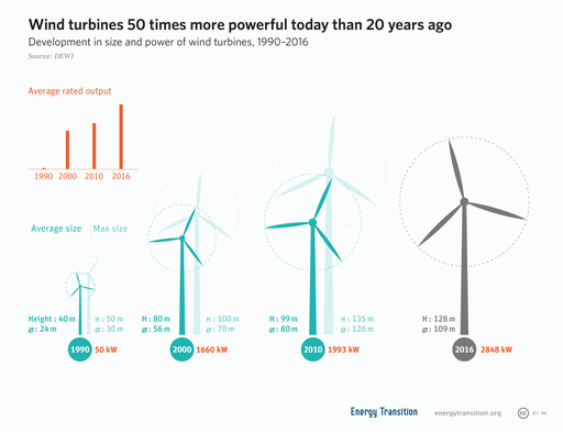
Turbine sizes vary widely, as seen in the diagram above. However, two things hold mostly true: Turbine sizes have grown over the years and offshore turbines are much larger than onshore turbines.
Component Overview
Let’s dive into what’s inside one of these behemoths. We’ll start from the blades and work our way in.
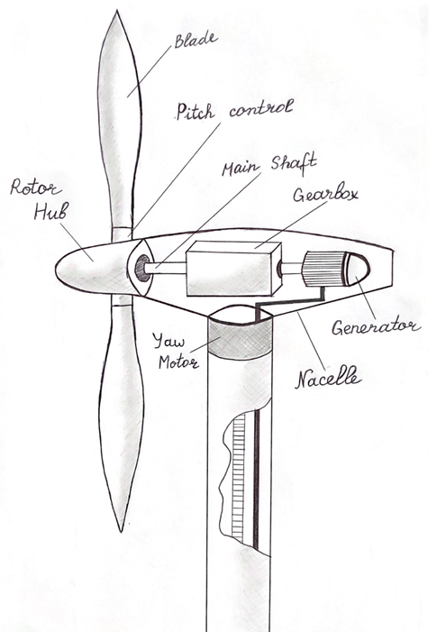
Blades, Rotor Hub, Pitch Actuators and the Nacelle
The blades that capture the wind are often made from a mixture of different materials, such as glass or carbon fiber, aluminum, and balsa wood. The blades also have extra equipment that aren’t particularly relevant to us, such as lightning protection systems and anti-freeze capabilities.
The blades are attached to the rotor hub, which also, like the rest of the turbine, contains sensor equipment, and (generally) three pitch actuators. The pitch actuators are used to pitch (rotate) the blades.
Pitching the blades is used to control how much power the turbine generates, which is often referred to as power control. Pitching the blades is also used for braking the turbine if the weather conditions or maintenance necessitates it.
The rotor hub is attached to the Nacelle, which is the name for the large encasing that contains all the other components. The nacelle has an anemometer on top to measure wind speed, a wind vane to measure wind direction, cooling systems and so forth.
Inside the Nacelle
Let’s look at the inside of the nacelle.
The rotor hub with the blades is connected to the rotor shaft (sometimes called the main shaft), which is a large hollow shaft that carries both power and data cables. Electricity and data is transferred from the non-rotating nacelle to the rotor shaft via slip rings.
The large, powerful but slow rotation from the rotor shaft is carried into the gearbox.
We’re not going to dive into the specifics of how a gearbox works, but the brief summary is that it turns the large powerful rotations of the main shaft into quicker rotations that the generator can use to generate power.
A gearbox is generally the heaviest part of the turbine, which is why it’s often seen at the center of the nacelle.
The rotations from the gearbox travel into the generator. The generator is generally a Doubly Fed Induction Generator type of generator. The details aren’t particularly relevant right now, but if you’re interested in a learning more this video is a decent to how generators work.
For larger turbines, the power is then fed into a high voltage transformer, which turns the low-voltage current from the generator into a high-voltage current. This is so it can be transmitted without losing too much power on the way.
Aside: Direct Drive Generators
We’ve talked about gearboxes and generators here, which is how most turbines have looked for a long time. In the last years, some companies have started exclusively using Direct Drive technology to generate power, replacing the gearbox and the generator entirely.
Instead of a gearbox and an induction generator, direct drive technology consists of a large ring of magnets between the rotor hub and the rest of the nacelle.
The magnets combined with the rotating main shaft, then act as a generator, with no gearbox required.
Direct Drive technology is expected to be more efficient and require less maintenance. On the flip side the power output varies with rotational speed, so extra equipment is needed to stabilize the power output before it reaches the grid. It also requires a lot of rare-earth metals.
If you want to know more about Direct Drive technology, see here [1], [2], [3].
Tower and Yawing
Whichever way you end up generating power, it must exit the turbine for the whole endeavor to be worthwhile. The power exits through some large power cables that hang down the tower.
Apart from power cables, the tower usually has ladders and lifts so that personnel can enter the nacelle.
Before we make it to the bottom of tower however, we need to talk about something that’s at the top of the tower. The yaw motor. This is used to yaw(rotate) the nacelle so that they point in the current wind direction.
The fact that turbines yaw comes with an intriguing consequence. If the turbine keeps yawing in the same direction, the cables hanging down the tower will get twisted and eventually damaged. To avoid this the yaw motor is also used for “unwinding” the turbine. If the turbine has yawed too far in one direction, it will have to pretend to be a ballet dancer and do a few turns the other way to avoid the power cable snapping.
Foundation and Grid Connection
The tower rests on a foundation that keeps it from falling over. Foundations are complicated and costly, especially for offshore turbines. However, these components aren’t something we’ll have to worry too much about as software developers.
The turbines in offshore wind parks are generally connected to some sort of offshore substation which transforms the voltage further before sending it on land.
--------------
If you’re interested in a little more of a visual tour this video is a good start. It is more than ten years old by now, but many of the principles are still the same.
While turbines have more components than this, such as parking brakes, local override switches and more, this overview will cover most of the large components.
Written by Gustav Wengel, Software Engineer at SCADA MINDS.
Read more on Gustav's code adventures here.